
CHASSIS UPGRADE
Overview: Stiffened frame, custom swingarm, large diameter hollow axles, Astralite wheels (18x3.5 front, 18x4.5 rear), 42mm Forcelle Italia forks, 320mm floating Brembo brakes,custom triple clamps & spindle, 'modernise' steering geometry to 26deg rake and 100mm trail.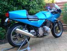
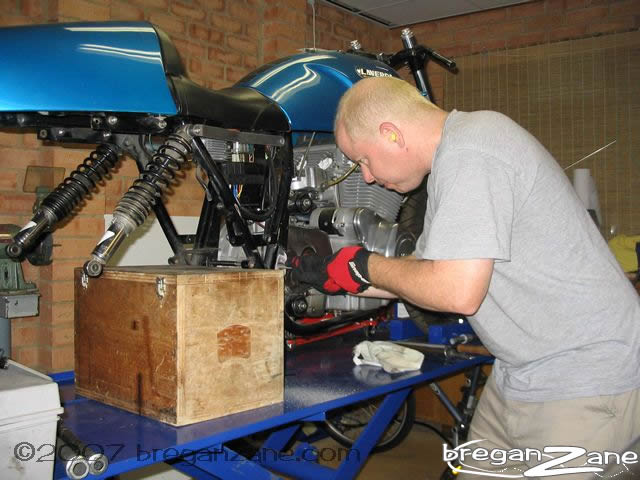
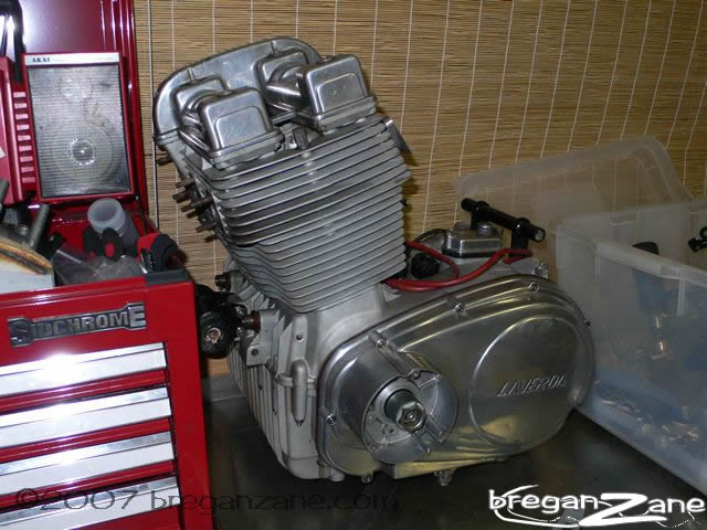
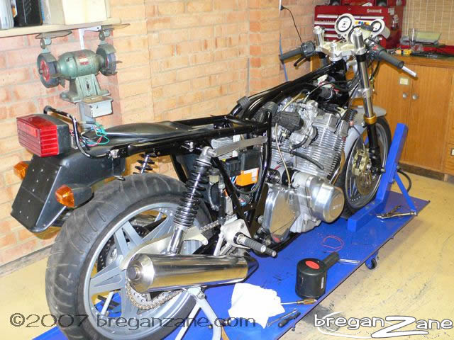
This is the bike my Dad bought new in 1985, and which I bought from him in 1992 when I was 20. Some years back a small bit of work on the engine snowballed into a complete top end upgrade, punching it out to 1130, getting 4C cams, a worked head, big exhaust and so on. Later came an IIS ignition, Axtell cams, and Mikuni CV carbs. The motor went really well and I soon started to see the shortcomings of what was now an overstretched chassis- the bike exhibiting some interesting weaves and wallows when the going got tough.
My good mate Thomas Hauge thought he would help me out by throwing the #2 conrod out of his Mirage special, and decided to part the bike out - a great shame which I tried to talk him out of. But he was resolute so I bought all the good chassis bits- Astralite wheels, Forcelle Italia 42mm forks, and lovely Brembo billet brakes. The chassis upgrade had begun...
 |
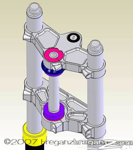
The overall objective was to get the bike rolling on larger modern radial tyres, stiffen the overall chassis structure, and improve the steering response. The first part was to carefully measure and 3D model the Laverda frame and all the parts I had bought. A little while later I had something like what is shown to the left. Straight away it was clear that a new swingarm would be required to fit the 160/60-18 rear tyre, and also that the triple clamps provided with the Forcelle Italia forks had an unsuitable offset to use with an 18" front wheel. |
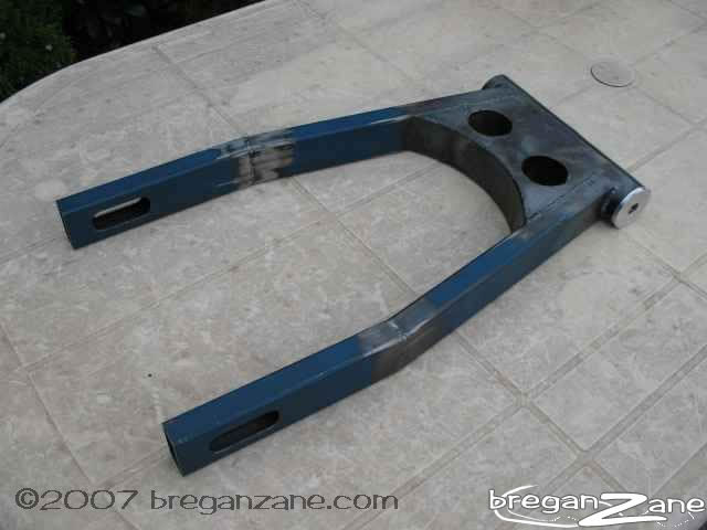 |
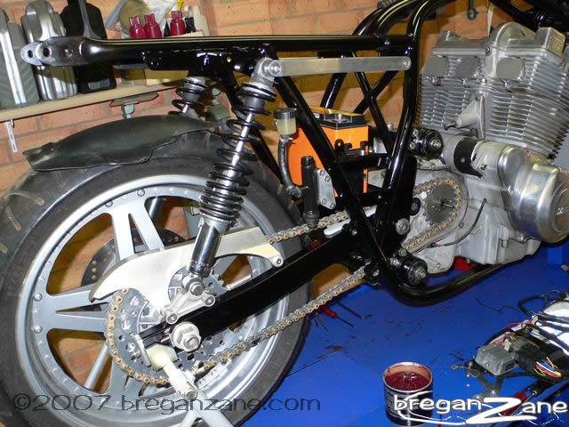
First piece I
constructed was the swingarm, which I based on a MacIntosh item, though
with a larger pivot tube (51mm) and bracing similar to a Bimota DB1.
Construction is simple ERW rectangular steel and steel sheet all TIG
welded up. The result is lighter and stiffer than the original (especially
at the wheel end) and keeps with the early 80's musclebike look I
am going for - huge ally swingarms weren't really in vogue yet then.
I toyed with the idea of a monoshock conversion but the added work
put me off. In actual fact the swingarm you see here had to be scrapped because (even though it was firmly jigged) it sprang in by about 10mm when I welded the centre web into it, welding distortion is a real bugger! You live and learn, using a different jigging and welding procedure the second came out spot on. |
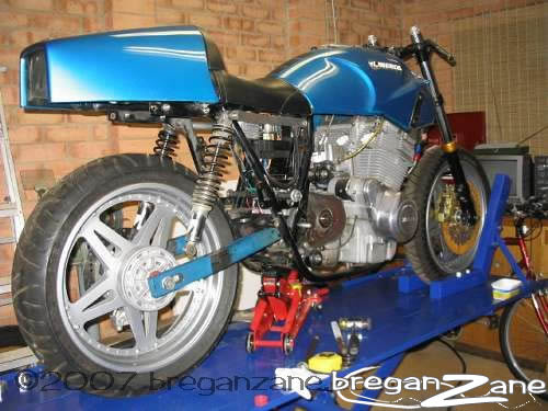 |
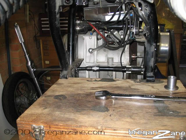
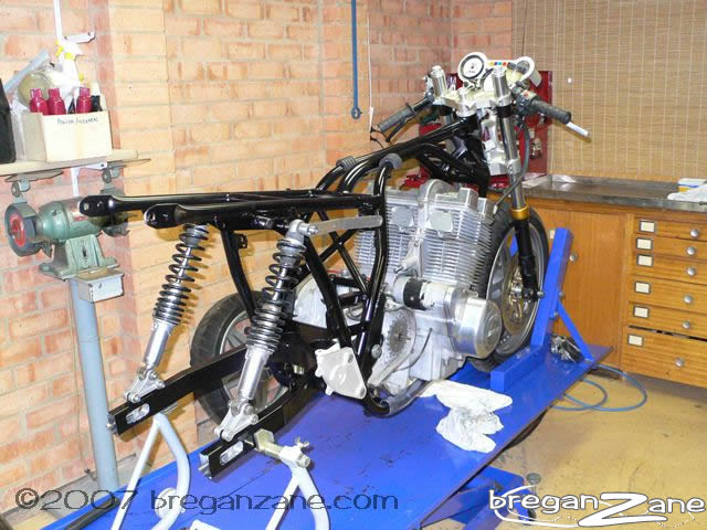
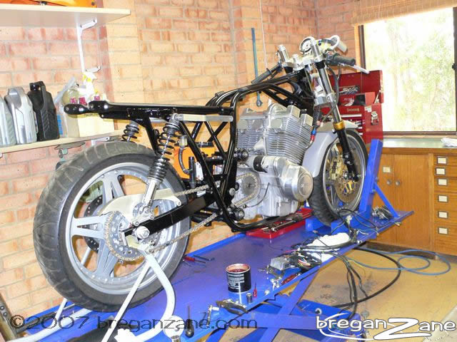
So at this stage I was able to roughly piece together the entire bike with the new components, though looks certainly deceive here because the bike is far from finished. |
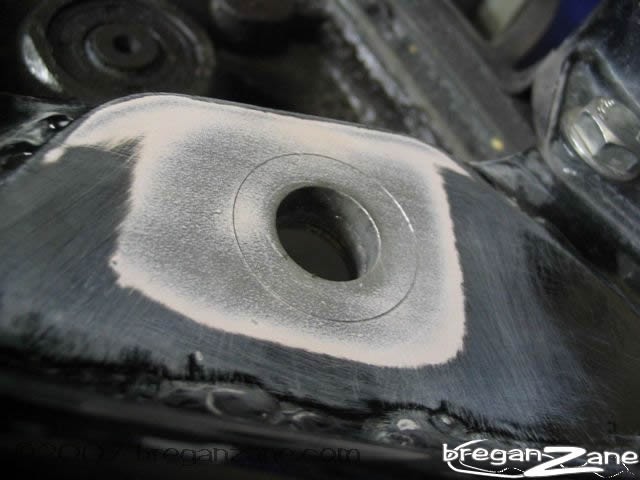
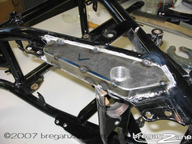
Next up was improving the frame. Many people have trod this path before (thanks Thomas Hauge, Sander Habets, Chris Pritt & others) so I was able to base my modifications on what the factory and various owners have done over the years. I worked on improving the stiffness of the frame in three main areas; steering head, swingarm pivot and the link between the triple spine tubes and swingarm pivot.
I made up a stepped
punch to mark the new diameter of the pivot holes, which were laboriously
filed out (the factory plate is 10.5mm thick here!!), then reamed to final
size (using a guide through the hole in the other side) until a stepped
bush was a knock-in fit. This procedure was then repeated on the other
side and the bushes jigged together in alignment. Thin sheet was fabricated
to box the whole structure together, the whole lot TIG welded up and after
all welding was completed the bushes - machined slightly undersize - were
reamed to finish size (once again using the opposite side as a guide)
thereby retaining perfect alignment. The new 20mm hollow spindle is now
a perfect sliding fit through both holes.
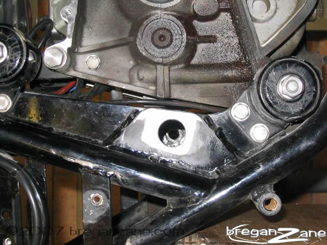
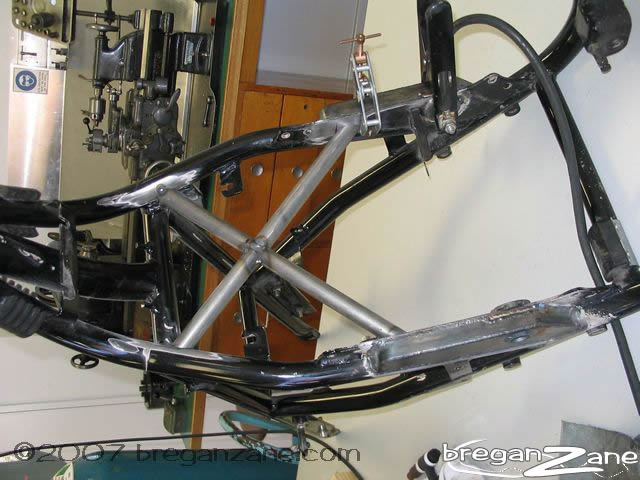
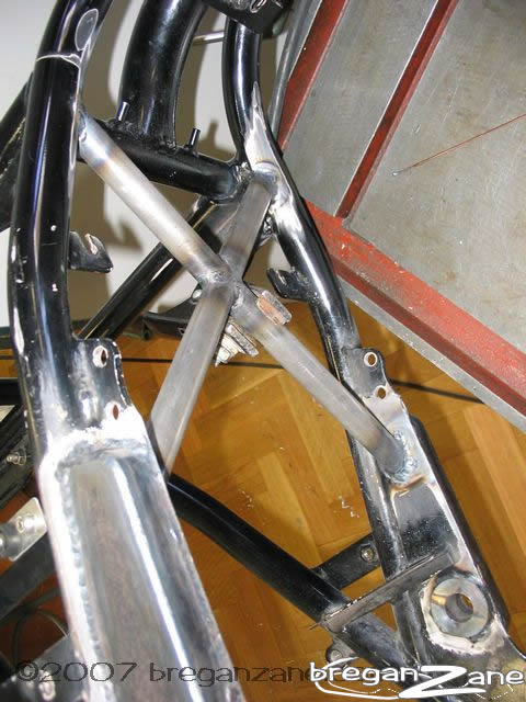
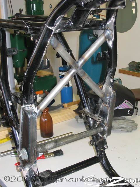
Looking at the structure of the frame, it is obvious there is an open
square between the outer spine tubes and the swingarm pivot. When the
swingarm pivot is trying to twist itself in relation to the headstock,
the frame has no triangulation in this point. I wanted to feed the forces
from the swingarm pivot more directly to the large triple-spine tubes,
so I fabricated a diagonal brace from the top of the new boxed-in pivot
plates to near the seat rail attachment point. I knew at the time this
would mean the original air box would not fit (no problem, my Mikuni one
would have), and even back then I had a sinking feeling I was probably
going a bit overboard here. Not sure if I would do the diagonal brace
again, it does greatly reduce the space available for fitting the EFI
components. Mind you, the bike now handles perfectly, so who's to say
how much the diagonal brace is contributing to that?
 |
 |
 |
 |
 |
 |
 |
 |
 |
 |
 |
 |
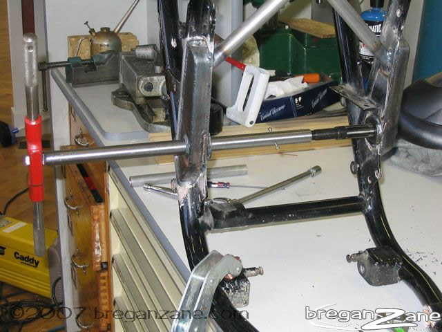
When turning to the
steering head, I based my modifications on the factory bracing kit from
the 80's and worked from there. Looking at modern sportsbikes, they have
a larger diameter bottom steering head bearing, and a tapered spindle.
Chris Pritt theorised that part of his weave came from the steering head
spindle flexing, some claim to have cracked their spindles, though I suspect
this may be more to do with accident damage.
I knew that with the ride height I intended to use I would have a little
bit of space left between the fork slider and the bottom triple clamp
at full compression, I wanted to reduce this to near-zero as it means
the forks are not hanging out unsupported as much. So there was just room
to fit an extension bush into the headstock, to accept a 32005 bearing
which has a 30mm ID, up 5mm on the original, allowing for a stiffer steering
spindle.
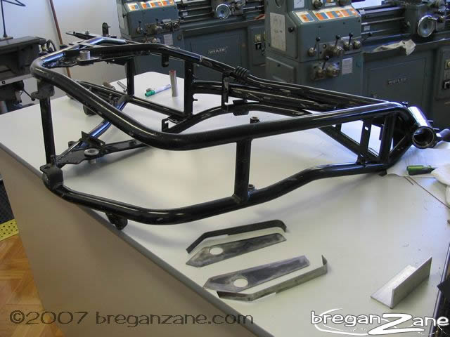
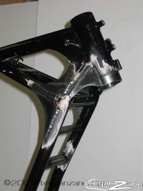
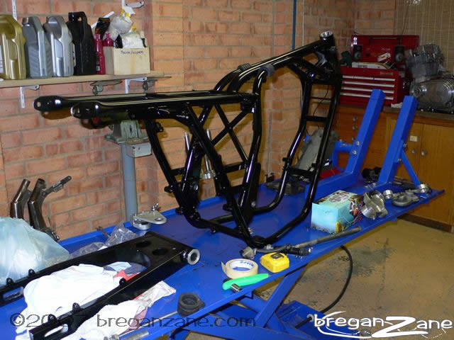
When the paint was stripped I found that the frame (a one-owner never
crashed bike) was cracked in the 'normal' place where the downtubes meet
the steering head, it's clear that the downtubes must be flexing for those
cracks to arrive. Once again standing back and looking at the structure,
I worked on providing a path for the forces at the lower steering head
bearing to be fed into the downtubes and outer spine tubes - basically
tying that whole area of the frame together into a single unit. This worked
in well with my extended steering head housing, as the gussets on that
neatly triangulated down to the outer spine tube / down tube joint. I
also added the extra tube above the headers, as per the factory bracing
kit.
 |
 |
 |
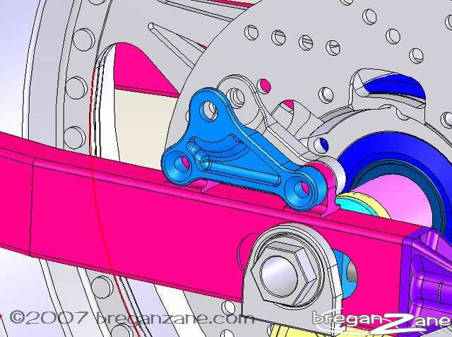
Growing tired of welder's-flash
and holes burnt in my jumper, it was time for some machining jobs. A few
hundred hours of fiddling and changing my mind soon saw a nice design
for triple clamps in front of me on the screen, including a +/-5mm adjustable
offset provision, allowing a little tuning of the trail if required. My
only other motorcycling weakness is for Bimotas, and all the machined
parts I have designed are heavily influenced by those Italian works of
art. Along the way the design got more elaborate, and I included some
pretty funky 3D machining in my design. But first I made a practice out
of the brackets for the rear shocks, these are intended so that I can
make ones of different heights, allowing major changes to the rear ride
height without welding new brackets on the arm all the time. Also for
the "bling" factor 'coz they look cool.
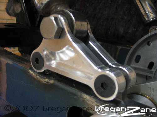
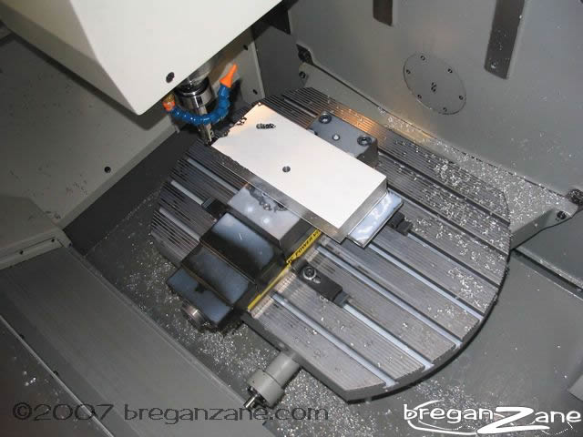
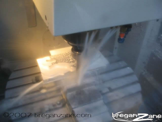
I operated a CNC milling machine almost 15 years ago but technology has
changed completely since then, with after-hours access to a nice new CNC
mill and CAM software I dived into this interesting new world of technology
with instruction from good mate and former Laverda owner Steve H. As a
practice these were great as they're pretty small and incorporated both
relatively simple 2D profiling and also the 3D milled pocket on the outer
faces.
For those not up to date with the lingo in this arena, CAD means computer aided design, CAM means computer aided manufacturing and CNC means computer numeric controlled (machine). The process goes; 1. design your part in CAD, producing a full 3D model, 2. import that model into the CAM software, 3. select and apply appropriate tools to cut the geometry you require, 4. have the CAM software generate the CNC code, 5. transfer the code to the CNC milling machine, 6. set up all the tools required by the program, 7. clamp your workpiece in the machine (often requires making jigs), 8. set up the workpiece's datum points in X,Y and Z, 9. run the program, 10. pray you got it right... the results of even the slightest error can be catastrophic - the machine will happily drive a several hundred dollar carbide cutter into a several thousand dollar hydraulic vice if you tell it to... making lots of very expensive noises in the process...
 |
 |
Okay, so far so good. But don't be fooled into thinking this stuff is just point and shoot - there are still many hours of work to program and set up to do even a small part like these. Actual machining time is pretty short cutting at up to 9000rpm in aluminium, but the entire job is still painfully drawn out. |
Over a period of several months the design of the triple clamps was refined. Learning as I went, the CAM process was completed using a lot of trial and error (you can preview the machining operations on the screen), needing to learn not only the software but also how to properly use the amazing tooling for these CNC machines. I ordered in a couple of lumps of 6061-T6 and off we went...
 |
 |
 |
|||||||||||||||||||
|
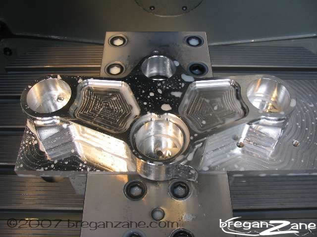
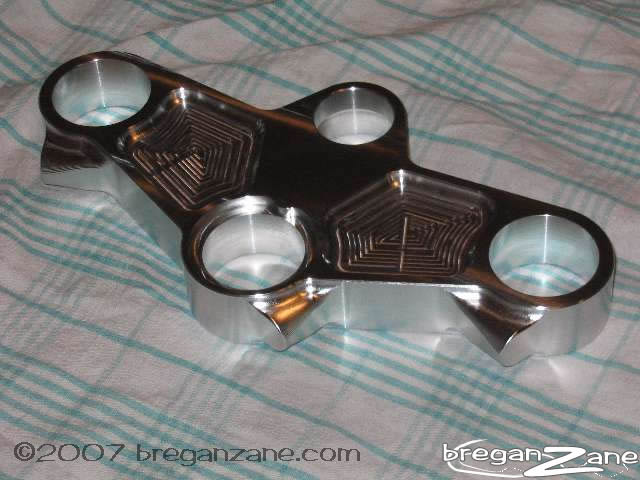
I must admit to being totally chuffed at how this worked out, after lots of caution in the preparation, machining went very smoothly. Shown here, the top clamp just needs the engraving and all the slits and bolt holes (machined manually). Now for the bottom clamp... The bottom clamp was somewhat more difficult, due to the fact it was twice the thickness. Cutting the small radii in the corners was more difficult due the the extra unsupported length of the tool cutting 50mm plate, but we got there with a few changes to the program and a bit more patience. The end result is pretty nice still...
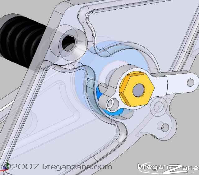
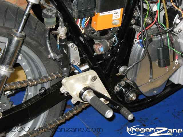
Finishing off the clamps required setting up in a manual milling machine and cutting the slits for the clamps, and drilling, tapping and counterboring the bolt holes. E'voila! One set of triple clamps! At this stage it's February 2006, and there was a solid nine months more work ahead of me to get it to the running stage. I'm trying to remember exactly what it all was. There were the adjustable inserts for the triple clamps (just zero offset ones to start with) the new spindle itself - tapered, hollow, made from 2738, turned, the bearing areas ground, and the two threads manually cut. Of course the nuts to fit those also had to be made. Unfortunately I don't have photos of that stuff as my digital camera packed it in during the year and I was too skint to get another one. It was amazing how much had to be made, and how long it all took. Basically I had to make every single piece in the front and rear ends, and a few things in between. Simple things like a rear brake toque arm (make rod, source rod ends, make frame tab, weld frame tab etc) might take a week or more, squeezing a couple of hours in 2-3 nights a week and working however much of the weekend you could. It really crushed you after a time, and at one point I was so lost in what still needed to be done it was all too much. At that point, take a week off and don't think about it at all, then, back in the shed, find one particular part that needs doing and do that, then the next... one foot in front of the other. It felt like a marathon. The footpegs
were probably the most significant job of the latter part of the
build-up, I wanted something that really looked good. They had to
blend well with the bodywork, and have a nice method of holding
the pipes. I was reusing my trusty Staintunes (great pipes!) only
angling them up a fair bit more than standard - enough so I could
remove the rear axle without having to take off a pipe. The rear
brake actuation also had to be neat, I wanted to maintain the original
RGS style of a hidden brake master cylinder, so the actuation had
to pass through the footpeg plate somehow - and I wanted it to be
hidden. And to add lust a little more complication there was only
a limited amount of room between the footpeg plate and the new wider
swingarm...
The front mudguard was another exercise in frustration. When I repainted Christiane's bike I had a mould taken off the SFC1000 front guard, knowing that my original RGA guard wouldn't suit the new forks due to the different mounting points. It was only AFTER I had the replica guard made (fibreglassing is one job I do get someone else to do) that it dawned on me it wasn't wide enough for the 120/70 front tyre! D'oh. But the SFC guard has detents to clear the forks that weren't required for my bike (I'd spaced the forks wider) so I spent a day filling the fork detents in the replica guard with bog and sanding the whole thing back, then took that out to have a mould made from it and a new guard made from that. Of course it was only when all that was over, and I fitted the guard, that I realised it's basically pretty ugly anyhow and doesn't really have the correct radius to look good against the wheel.... Sigh, it's doing the job for now. Anyhow, you get the idea, it was a few months of making all manner of little bits and bobs like the fork brace, wheels spacers and stuff (getting the 25mm rear axle to fit the original cush drive was interesting in itself), fitting things and finding out what did and didn't work, sorting out all the little details. I made a really nice fairing bracket in aluminium tube, sand bent and all, weighs almost nothing (shame about the 5kg of instruments hanging off it!) and seems to be strong enough so far . Eventually it was time to pull it all down and give the frame a coat of paint and reassemble!
After all that work the reassembly only took two days! Just needed a new rear brake hose made and it's on the road again at last! Did a 4000km trip over New Year and the only thing to fail was my slightly-too-flimsy chain guard Handling is rock solid, turns nicely and just the occasional head-shake hitting bumps under power, most of which has been dialed out with some fork damping adjustments. The Racetech-revalved shocks perform really nicely, the front a little harsh and could possibly do with Racetech emulators down the track, or perhaps just some lighter oil and some fiddling. A taller seat than standard and pretty low bars put you much more over the front wheel. In terms of handling it is now very much like my Bimota YB8 believe it or not - it's actually quite similar to ride (though obviously not as quick). A track day is required to really see what it does when going semi-fast. |
|||||||||||||||||||||


And so that is basically it. I'm very happy with it all and am now moving on to the EFI..... stay tuned.
